
Imagine walking into your home after a long day, only to be greeted by the shrill blare of a smoke alarm. It’s a terrifying experience, and it highlights the crucial role that smoke detectors play in protecting our lives and property. Among the various types of smoke detectors, duct smoke detectors are particularly important, ensuring that smoke is detected early and efficiently within a complex network of air ducts. Understanding how to wire these detectors is essential for ensuring optimal performance and safety. This article delves into the intricacies of System Sensor duct smoke detectors, providing a detailed wiring diagram and valuable insights for homeowners and technicians alike.

Image: life-improver.com
The importance of duct smoke detectors cannot be overstated. These devices are strategically placed within air duct systems, enabling them to detect smoke and trigger alarms before it reaches living areas. By doing so, they provide valuable early warning, giving occupants ample time to evacuate safely. But before we dive into the specifics of wiring, it’s important to understand the fundamental principles behind these devices and the different components that make them work.
Understanding System Sensor Duct Smoke Detectors
System Sensor is a leading manufacturer of fire safety equipment, including a wide range of duct smoke detectors. These detectors employ advanced technology to sense the presence of smoke in airflow, even in the early stages of a fire. The key component is a sensing chamber, typically containing an ionization or photoelectric sensor.
When smoke particles enter the chamber, they trigger a response from the sensor. In ionization detectors, smoke particles ionize the air, disrupting the flow of electrical current and triggering an alarm. Photoelectric detectors, on the other hand, utilize a light beam. Smoke particles scatter the light beam, triggering an alarm. These detectors are designed for high-sensitivity environments like commercial buildings, industrial facilities, and large residential complexes.
System Sensor Duct Smoke Detector Wiring Diagram
The wiring diagram for a System Sensor duct smoke detector typically involves multiple connections to ensure proper operation and integration. The diagram will vary depending on the specific model and the system configuration. However, some common components and connections include:
- Power Supply: Most duct smoke detectors require a 24V DC power supply, which can be provided by a central control panel or a dedicated transformer.
- Alarm Output: The detector’s alarm output signal is connected to the control panel, triggering an alarm if smoke is detected.
- Supervisory Circuit: This circuit is used to monitor the status of the detector and signal any faults or failures to the control panel.
- Remote Annunciator: This optional connection allows for the alarm to be signaled to a separate remote location.
- Termination Resistor: This resistor ensures proper signal transmission within the system.
Understanding the Parts of the Wiring Diagram
The System Sensor duct smoke detector wiring diagram is a visual representation of the connections between different components within the system. It typically includes:
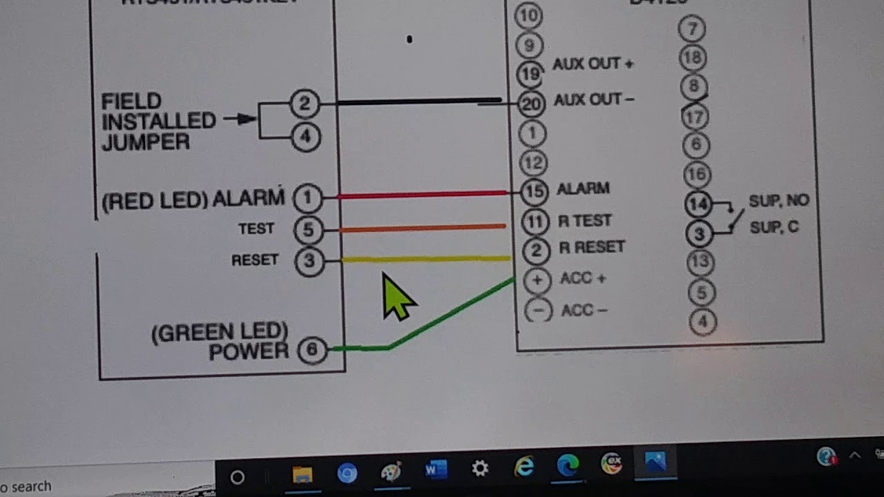
Image: schematicdiagramsaenger.z13.web.core.windows.net
Terminals
These are the points on the detector where wires are connected. The diagram will label each terminal with a letter or symbol to indicate its function.
Wires
The diagram will show the different wires connecting the detector to other components in the system. Each wire is labeled with a number or color code to indicate its purpose.
Symbols
The diagram will use various symbols to represent different devices, such as power supplies, control panels, and annunciators. Each symbol will be defined in a legend.
Interpreting the Wiring Diagram
The wiring diagram is a critical tool for understanding the operation of the duct smoke detector system. By following the diagram, technicians can:
- Connect the detector to the power supply and control panel.
- Ensure proper wiring for the alarm and supervisory circuits.
- Identify any potential troubleshooting issues.
It’s essential to closely examine the specific wiring diagram provided by the manufacturer for the particular model of System Sensor duct smoke detector you are installing. These diagrams are comprehensive and will provide detailed instructions for ensuring correct connections.
Tips for Proper Wiring
Following proper wiring practices is crucial for safe and reliable operation of your duct smoke detector system. Here are some key tips:
- Use the Correct Wire Gauge: The wiring gauge should be compatible with the detector’s specifications and the current requirements of the system. Consult the manufacturer’s documentation for recommended wire gauge and type.
- Ensure Secure Connections: Tighten all wire connections securely to prevent loose connections that could cause intermittent performance or failure.
- Label Wires Clearly: Label each wire with its function, using tape or other suitable marking materials. This will make it easier to troubleshoot the system in the future.
- Use the Correct Tools: Utilize appropriate tools for stripping wire insulation, crimping terminals, and making connections.
- Test Thoroughly: After completing the wiring, test the system to ensure all detectors are functioning correctly. Follow the manufacturer’s recommended testing procedures.
Expert Advice
When working with duct smoke detectors, consulting with experienced professionals is highly recommended. These professionals possess in-depth knowledge of fire safety regulations and can provide customized advice based on your specific needs. For example, they can help you determine the optimal placement of detectors within the ductwork system, taking into account air flow patterns and potential fire hazards.
Another critical aspect is ensuring the detectors are regularly inspected and maintained. This includes checking for dust buildup, cleaning the sensing chambers, and verifying that the alarms are functioning properly. By staying proactive with maintenance, you can significantly reduce the risk of detector failure and ensure the safety of your property and occupants.
FAQs on System Sensor Duct Smoke Detectors
Q: What are the key differences between ionization and photoelectric smoke detectors?
A: Ionization detectors are more sensitive to fast-burning fires, while photoelectric detectors are more sensitive to smoldering fires. The type of detector you choose depends on the specific fire risks in your environment.
Q: How often should duct smoke detectors be tested?
A: It’s recommended to test duct smoke detectors monthly to ensure they are functioning correctly.
Q: What are some common wiring mistakes to avoid?
A: Some common wiring mistakes include using incorrect wire gauges, loose connections, and failing to label wires properly.
System Sensor Duct Smoke Detector Wiring Diagram
Conclusion
Understanding the System Sensor duct smoke detector wiring diagram is essential for proper installation, troubleshooting, and ensuring the safety of your facilities. By following the guidelines outlined in this article, you can build and maintain a reliable smoke detection system that provides early warning and protects lives. This knowledge empowers you to make informed decisions regarding your fire safety systems.
Are you interested in learning more about duct smoke detector systems, or perhaps you have a specific question about wiring diagrams? Please share your thoughts in the comments below. We’d love to hear from you!


