
Have you ever pondered the intricate network of sensors that keep your Cummins ISX15 engine running smoothly? These tiny components, strategically placed throughout the engine, act as silent sentinels, monitoring vital parameters and feeding crucial information to the engine control unit (ECU). Understanding the location of these sensors can be instrumental in diagnosing problems and ensuring your engine’s longevity. Let’s embark on a journey of discovery, unveiling the secrets of the ISX15 Cummins ISX sensor location diagram, a roadmap to maintaining peak engine performance.

Image: www.youtube.com
This diagram, a visual representation of the sensor network, serves as a valuable tool for mechanics, technicians, and even knowledgeable truck owners. It provides a precise layout of each sensor, allowing them to easily pinpoint their location, identify potential issues, and troubleshoot effectively.
The Heart of the Engine: Sensor Roles and Functions
The ISX15 Cummins ISX engine relies on a sophisticated network of sensors to gather vital information and enable precise control. Each sensor serves a specific function, contributing to the engine’s overall performance and efficiency. Let’s explore the key players in this intricate system:
1. Temperature Sensors: Keeping Things Cool
- Coolant Temperature Sensor (CTS): Monitors the temperature of the engine coolant, crucial for regulating the engine’s operating temperature.
- Oil Temperature Sensor (OTS): Measures the temperature of the engine oil, providing insight into lubrication efficiency and potential overheating issues.
- Intake Air Temperature Sensor (IATS): Measures the temperature of the air entering the engine, ensuring optimal combustion conditions.
2. Pressure Sensors: Maintaining Equilibrium
- Oil Pressure Sensor (OPS): Detects the oil pressure within the engine, signaling potential lubrication problems.
- Fuel Pressure Sensor (FPS): Monitors the fuel pressure at the injectors, ensuring proper fuel delivery.
- Boost Pressure Sensor (BPS): Measures the pressure generated by the turbocharger, crucial for regulating power output.
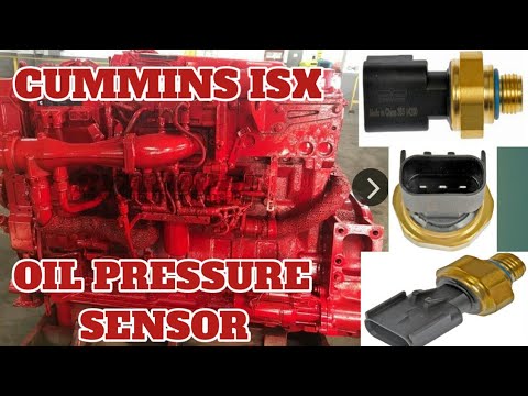
Image: wiringdiagramsite.blogspot.com
3. Position and Speed Sensors: Timing is Everything
- Crankshaft Position Sensor (CKPS): Determines the crankshaft’s position, essential for ignition timing and fuel injection.
- Cam Position Sensor (CPS): Measures the camshaft’s position, ensuring proper valve timing and fuel delivery.
- Vehicle Speed Sensor (VSS): Tracks the vehicle’s speed, enabling cruise control and other functions.
4. Oxygen Sensors: Monitoring Combustion Efficiency
- Exhaust Gas Oxygen Sensor (EGO): Measures the oxygen content in the exhaust, helping the ECU adjust air-fuel ratio for optimal combustion.
Navigating the Sensor Landscape: A Deeper Dive
Now, let’s dive deeper into the specific locations of these sensors on the ISX15 Cummins ISX engine, using the sensor location diagram as our guide. Understanding these locations will empower you to diagnose problems, perform maintenance, and ensure optimal engine health.
1. Fuel System: From Tank to Combustion Chamber
- Fuel Pressure Sensor (FPS): Typically located on the fuel rail, close to the injectors. It monitors the pressure at which fuel is delivered to the injectors.
- Fuel Level Sensor (FLS): Residing within the fuel tank, it measures the level of fuel present, providing an indication of fuel reserves.
2. The Air Intake Path: From Atmosphere to Engine
- Intake Air Temperature Sensor (IATS): Often positioned after the air filter, measuring the temperature of the air entering the engine.
- Mass Airflow Sensor (MAF): Installed in the intake manifold, it measures the amount of air entering the combustion chamber, crucial for air-fuel mixture calculations.
3. The Exhaust System: Clearing the Way
- Exhaust Gas Oxygen Sensor (EGO): Typically located in the exhaust manifold or in the exhaust pipe after the catalytic converter, monitoring oxygen levels in the exhaust gases.
4. Lubrication System: Keeping Things Moving Smoothly
- Oil Pressure Sensor (OPS): Mounted on the engine block, it measures the pressure of the oil circulating through the engine.
- Oil Temperature Sensor (OTS): Placed in the engine block or oil pan, it monitors the temperature of the engine oil.
5. Timing and Control: A Precise Dance
- Crankshaft Position Sensor (CKPS): Located on the front of the engine block, near the crankshaft, it detects the crankshaft’s position, crucial for ignition timing and fuel injection.
- Cam Position Sensor (CPS): Found on the cylinder head or camshaft, it measures the camshaft’s position, ensuring proper valve timing and fuel delivery.
- Vehicle Speed Sensor (VSS): Typically located on the transmission output shaft, it measures the vehicle’s speed, providing crucial input for cruise control and other functions.
Decoding the Diagram: A Practical Guide
While the sensor location diagram provides a visual map of the sensor network, understanding its nuances can be crucial for efficient troubleshooting. Here’s a practical guide to deciphering the information on these diagrams:
- **Sensor Symbols:** The diagram usually uses unique symbols for each sensor type, making identification easier.
- **Sensor Labels:** Each sensor is labeled with a corresponding code or abbreviation, such as “CTS” for Coolant Temperature Sensor.
- **Wiring Diagram Integration:** The sensor location diagram often integrates with the engine’s wiring diagram, providing information on the sensor’s electrical connections.
- **Alternative Viewpoints:** Some sensor location diagrams may include multiple views of the engine, providing a comprehensive perspective.
The Importance of Accuracy: Avoiding Pitfalls
Accurate sensor location diagrams are vital for efficient troubleshooting and repairs. Using outdated or inaccurate diagrams can lead to misdiagnosis, wasted time, and costly mistakes. Always ensure you have the most up-to-date diagram for your specific engine model and year.
When searching for a sensor location diagram, consider the following:
- Engine Model and Year:** Specific models may have different sensor arrangements, so ensure the diagram is compatible with your engine.
- Reputable Sources:** Use trusted sources such as owner’s manuals, repair manuals, or reputable online resources.
- Manufacturer’s Information:** Consult the engine manufacturer’s website for official sensor location diagrams.
Isx15 Cummins Cummins Isx Sensor Location Diagram
Conclusion: Unlocking Engine Performance Potential
The ISX15 Cummins ISX sensor location diagram serves as a roadmap to understanding and maintaining the intricate network of sensors that power your engine. By understanding the function and location of each sensor, you can effectively diagnose problems, perform preventative maintenance, and unlock your engine’s true performance potential. The next time you’re facing an engine issue or simply want to gain a deeper understanding of your Cummins ISX15, remember that the secrets to optimal performance lie within this valuable diagram.


